


879
Recommended Guidelines for Arc-Flash Labeling
Whenever an arc-flash study is done or revised and new arc flash warning labels must be considered, it is a good idea to define exactly what information belongs on each label before starting to print anything. It is also a good idea to define how and where these labels will be applied before anyone peels the back off of the first adhesive label and sticks it onto anything. It is a very good idea to put those definitions into writing so that everyone who assists or who comes along later, has something to help them understand the original intent. This is particularly important as a means of trying to promote consistency and to avoid creating unnecessary confusion when an arc flash analysis study is spread out over extended period of time. A guideline document such as the one published here serves that purpose. The guideline describes how electrical equipment should be labeled, namely how many labels should be applied and in which locations, after appropriate data collection, modeling, short-circuit analysis and arc-flash study activities have been completed. The intent here is not to limit the number of labels applied but rather to insure that at least the required minimum number of labels are in place. This document also addressed the question of how to label devices that were subject to protection under a selectable maintenance settings scheme. This application involved two labels as shown in Figure 6.
The arc-flash labels discussed herein are required by the NEC in article 110.16 and by NFPA 70E in Section 130.7 (E)(1). There are two basic types of arc flash labels that should be used. They are a generic label - one that does not include specific calculated data but which identifies the existence of the hazard and refers the reader to the site 70E policy, and a specific label - one that includes calculated data for arc-flash incident energy or hazard/risk category and identifies specific required PPE. Figure 1 shows one of each type of label, with the generic type being the upper label. This guideline identifies what type of equipment we should be labeling and how to label that equipment. If a piece of equipment is identified by company guidelines as within the scope of equipment for which we should be calculating arc-flash exposure, then the label should be a specific label. Otherwise, the label will be a generic label and will refer to the overall site 70E policy. Wherever specific labels are applied, they shall describe all of the requisite PPE.
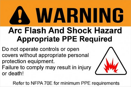
Figure 1A. An example of generic arc flash warning label.
Figure 1B. An example of specific arc flash warning label.
Many facilities have been through short-circuit and arc-flash studies conducted under previous versions of the NFPA 70E regulation. In such cases, it is possible that the labels already in place in the field reflect older hazard levels and types of PPE for some of the labeled equipment and are no longer correct for the current version of NFPA 70E. It is permissible to hand-modify the existing labels if the changes are somewhat minor, but it is often confusing to do that. The preferred approach is to relabel the equipment. However, since the current version of the regulation requires review and update on a five-year cycle, it is recommended that the labels simply be corrected during the course of the next overall update.
The generic label is a Brady product, while the specific label is a product printed as output from Arc Flash Analytic software program. Both of these labels use the ANSI Z535.4 "warning" format and an orange banner. The "danger" format with a red banner, described in the same ANSI standard, is equally acceptable.
General Guidance
In general, any door or access cover that can be opened or removed to expose energized parts with potential of >=50 V should bear a label. If there are multiple pieces of exposed equipment that have different associated shock or arc-flash values, the label should indicate the highest level of shock or arc-flash hazard exposed within the compartment. Any removable cover shall be marked to identify the specific compartment for which it is intended to be used. This general guidance is specifically modified as noted in Figure 1.
Low-Voltage Motor Control Centers
There should be one label on the incoming compartment cover or door (unless the MCC is bottom entry, in which case the label should be on the top wire far above the incoming compartment). If the MCC is more than five vertical sections wide, there should be an additional label on a top wire-way cover at the other end of the MCC. If the MCC was built in back-to-back configuration with a single source of power supply, there should also be an additional label near the center of the top wire way on the back side of the MCC. There does not need to be a label on every compartment. Figure 2 shows a 480V MCC with the incoming section (painted yellow) labeled for arc-flash hazard. The MCC is three sections wide and is not back to back, so no other labels are required. There are no labels on each individual starter compartment.
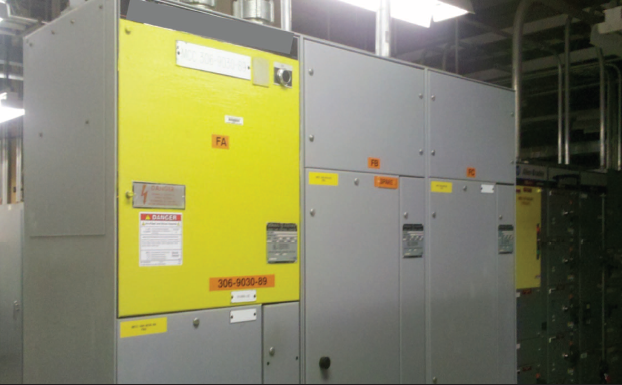
Figure 2. A 480-V MCC (three wide and not back to back).
MV (2,300 or 4,000 V) MCCs
There should be a label on the incoming compartment door or cover. There should be a label near each individual starter or switch operating handle. In addition, if there are any draw-out-type power drawers (for metering transformers, for example), those drawers should be individually labeled as well (see Figure 3).
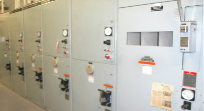
Figure 3. The front view of MV MCC (showing each compartment with a label near the disconnect).
Switchgear (15 kV, 5 kV, 600 V) with Draw-out Circuit Breakers
Every compartment that houses a draw-out device should have a label. There should also be a label on the covers for the incoming power compartment. Figure 4 shows the rear view of a 480V switchgear lineup with each compartment cover labeled. Figure 5 shows the front view of that same lineup of 480V draw-out switchgear with each compartment access door individually labeled.
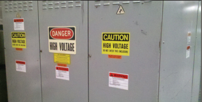
Figure 4. The rear view of 480-V switchgear. Note that there are labels on each compartment cover. Also note that there are two labels on the incoming section (at left). These labels relate to two different levels of arc-flash hazard/risk (see description in Figure 5).
Note that there are two labels on the incoming section (Figure 5). They depict the use of a maintenance settings group selector switch that has been installed in conjunction with an upstream breaker and is used to temporarily reduce instantaneous current trip settings during maintenance activities such as voltage testing and troubleshooting. This arrangement can also be useful for reducing arc flash in the rear compartments.
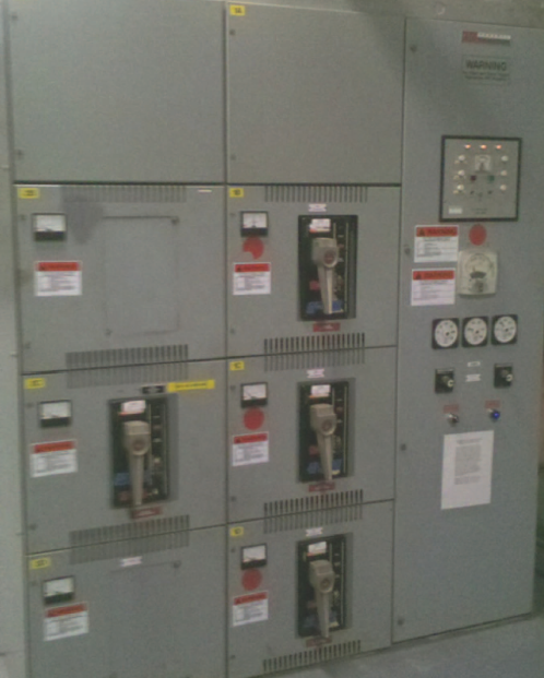
Figure 5. The 480-V draw-out switchgear with each compartment door labeled.
Panelboards
All distribution panelboards should bear arc-flash and shock hazard labels. If there is a main disconnect with a separate cover, that cover should bear a label for arc flash on the line side of the disconnect, while the cover for the rest of the panelboard should be labeled for the arc flash corresponding to the load side of the main disconnect. If there is a single cover, it should be labeled for the maximum arc flash available at any point on the exposed equipment. If the panel-board is to be labeled using generic labels, there should be a label on each separate cover piece.
Transformer Primary Switches
Each transformer primary switch should be labeled both front and rear (if rear access is available). The front label should be installed near the operating handle or handle access door. The rear label should be near the center of the rear access panel. If the switch is constructed so that any cover or door provides access to just a specific barrier-isolated section of the interior, that cover shall be labeled for the maximum hazard available in that particular section.
Multi-device Enclosures, Junction Boxes and Field-Mounted Devices
Any separately mounted device (including, but not limited to, starters, power switches, fuses, circuit breakers, and drives) that is constructed so as to be able to be opened for access to internal components for the purpose of testing, troubleshooting, or resetting shall be labeled for the highest level of arc flash available on any exposed internal component. This comment is fully intended to result in (at least) generic arc-flash labels being installed on all 600V class disconnect switches and motor safety switches.
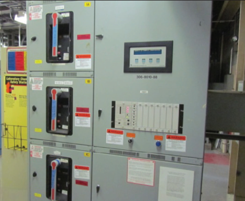
Figure 6. A view of 480-V switchgear utilizing the maintenance settings group protective scheme. Note the dual arc-flash labels, settings group selector switch, and indicator on incoming section.
Reference // Mitigating Arc Flash Hazards by Warren S. Hopper & Chuck Collins
Copyright © 2019 ARCAD INC. All rights reserved.