Single and three-phase arc flash calculations software
ARCMASTER version 1.0 software for Windows operated PCs has been developed as an easy to use and comprehensive tool for calculating arc incident energy and arc flash boundary. This software simplifies determining incident energy at working distance, arc flash, limited and restricted approach boundaries in single phase and three phase AC power systems when work is to be performed on or near the energized equipment. The program performs the analysis by taking into account equipment class, fault type, system voltage, available short circuit fault current and X/R ratio, conductor gap, working distance, protection device type and rating, or a preset arc duration value, and determines incident energy released by the arc flash, arc flash and shock protection boundaries and site-specific level of personal protective equipment (PPE). ARCMASTER V1.0 is applicable for systems with voltages in the range of 50 to 30,000V AC, short circuit fault currents from 0.2 to 50kA, the fault X/R ratios from 0 to 50, conductor gaps from 1 mm. up to the lesser of 300 mm. and the maximum value where the arc can likely be sustained under the specified system voltage, available short circuit fault current and the fault power factor.
ARCMASTER V1.0 software program for Windows PCs
ARCMASTER V1.0 program is now available for USD$290.00 by mail in disk format or via download from our web server. Payments can be made online using Visa or MasterCard credit card, through PayPal or any other acceptable payment form. The installation package and product registration key will be sent to you within 24 hours of placing your order.
About ARCMASTER V1.0
ARCMASTER V1.0 takes equipment class, fault type, system voltage, available short circuit fault current and X/R ratio, conductor gap, working distance, protection device type and rating, or a preset arc duration value, and determines incident energy, arc flash and shock protection boundaries. Arcing current can be expressed as a function of the length of the gap and arcing voltage. Arcing voltage can be derived as a function of arcing current, system voltage, available fault current and the fault X/R ratio. ARCMASTER V1.0 calculates arcing current using the iterative method by cycling through the equations for arcing current and arcing voltage until the answers converge. Next, the program will determine the arc duration based on protective device time-current characteristics and circuit time-constant. Lastly, the program will calculate incident energy at working distance, arc flash and shock protection boundaries. Check AC Arc Flash Modeling for more information. ARCMASTER V1.0 comes complete with a built-in library of selected protection devices and the capability to extend the library. The program will determine arc duration based on predicted arcing current value and selected protection device type and rating.
ARCMASTER V1.0 How To's
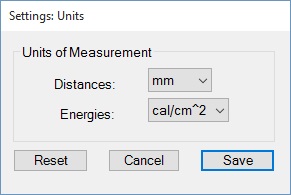
By clicking on Settings -> Units Of Measurement menu item, metric (mm, Joules) and imperial units (inches, calories) can be selected for gap between conductors, working distance, arc flash boundary, limited and restricted approach boundaries and incident energy.
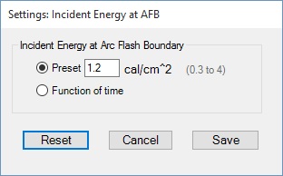
By clicking on Settings -> Incident Energy at AFB menu item, Preset or Function of time incident energy at arc flash boundary can be selected. With Preset option selected, enter a value in cal/cm2 or Joules/cm2 to determine arc flash boundary (AFB) distance at that incident energy. The incident energy of 1.2 cal/cm2 (5 J/cm2) for bare skin is commonly used in solving equations for arc flash boundary. However, the equations for arc flash boundary can also be solved with other incident energy levels as well such as the rating of proposed personal protective equipment (PPE). Values withing the 0.3 cal/cm2 to 4 cal/cm2 range are accepted in this program version.
For exposures lasting less than one (1) second the irradiance required for second degree burn at bare skin exposure would significantly increase as the duration of exposure decreased, however the amount of incident energy required to cause the burn would decrease. With Function of time option selected, the program will determine the amount of incident energy to second degree based on heat flux intensity and use that incident energy value to calculate the arc flash boundary.
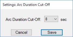
By clicking on Settings -> Arc Duration Cut-Off menu item, the designated upper limit of arc duration for incident energy and arc flash boundary calculations can be selected in 2 to 10 seconds range.
It's usually assumed that the outer limit for the arcing time is no more than 2 seconds. Although this is not a hard and fast rule, it accounts for the likelihood that the arcing material in an arcing field will likely be either burned off or expelled by the force of the blast. In any case, this would extinguish the arc event. Also, IEEE 1584 states "If the time is longer than two seconds, consider how long a person is likely to remain in the location of the arc flash. It is likely that a person exposed to an arc flash will move away quickly if it is physically possible and two seconds is a reasonable maximum time for calculations".
When arc duration exceeds selected arc duration cut-off, the program will report both actual arc duration and incident energy at ADC values.
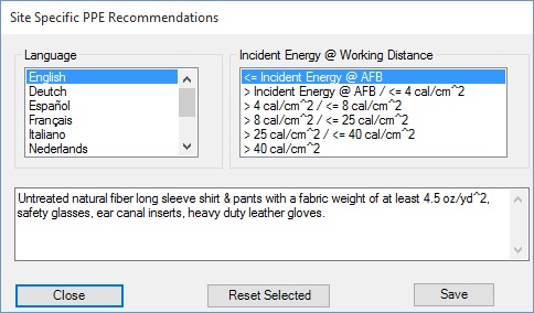
By clicking on Settings -> Site Specific PPE Recommendations menu item, personal protective equipment (PPE) recommendations displayed on labels created using the program can be reviewed, edited or reset to default values. The feature will let you making necessarily PPE adjustments required for various tasks in English and a variety of international languages. Also, the PPE requirements in new NFPA 70E standard have changed from previous editions of the standard. They may change again and the feature will let you reflect the changes as the safety standard evolves.
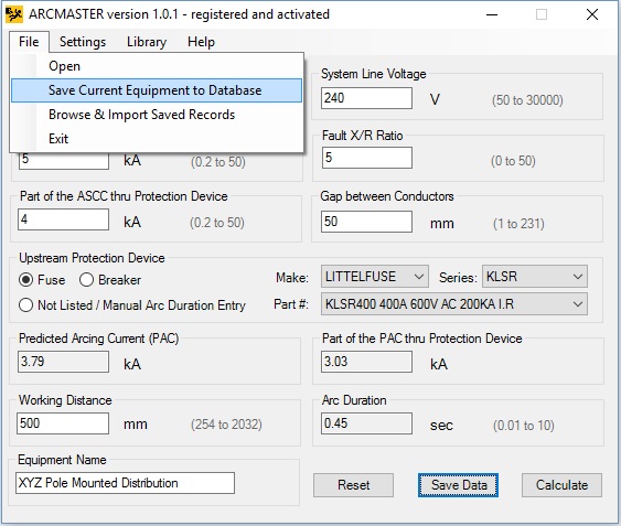
The program allows to save equipment configuration for future reference. Specify Equipment Name and select File -> Save Current Equipment to Database menu option to save the equipment configuration to database.
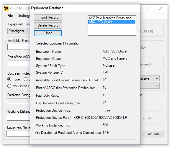
Select File -> Browse Saved Records menu option to open up the database containing saved equipment configurations.

Select a record and click on [Import Record] button to copy the data into the program main window.
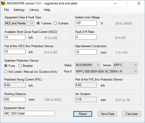
The program will populate input data fields with the selected equipment configuration.
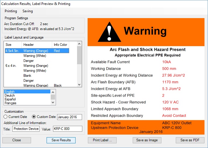
By pressing Save Result] button on Calculation Results, Label Preview & Printing screen, the results of arc flash analysis will be saved to a text file for future reference or printing. You can save results for different jobs under different names.
By choosing Open from File menu you can now open an existing results file, inspect its current content, do simple editing operations including Copy to clipboard and Save.

If you need more complex editing, import the file into your favorite text manipulation processor (MS Word as an example) and do what need to be done.
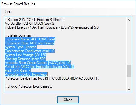
The program allows to create and save generated arc flash & shock hazard warning labels in electronic JPG, GIF, TIF, BMP (BitMap) and PDF formats.
Click on Calculate button on bottom right of the main program screen.
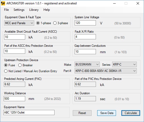
The Calculation Resuts, Label Preview & Printing screen will open up. Select label size, type, layout and language and click on one of the save buttons or Saving menu item to save the label on your drive in graphic or PDF format.
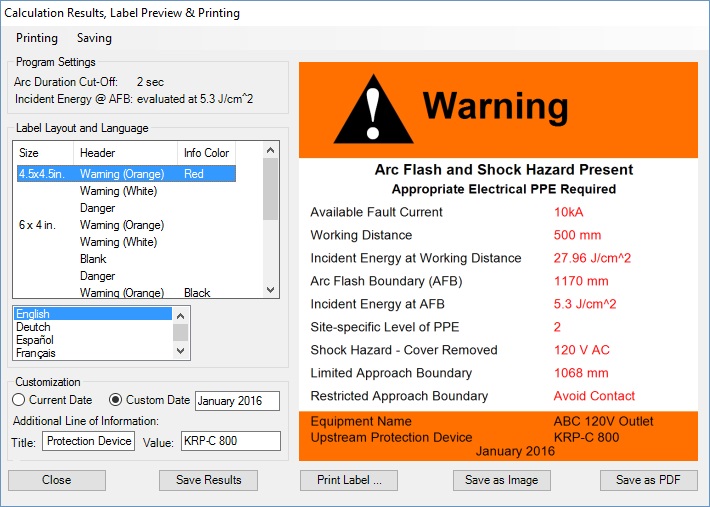
The program allows to send arc flash labels directly to print. Click on Calculate button on bottom right of the program main screen. The Calculation Results, Label Preview & Printing screen will open up. Select label size, type, layout and language and click on Print Label button or Printing menu Print Label ... item to send the label to print.
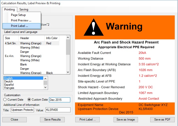
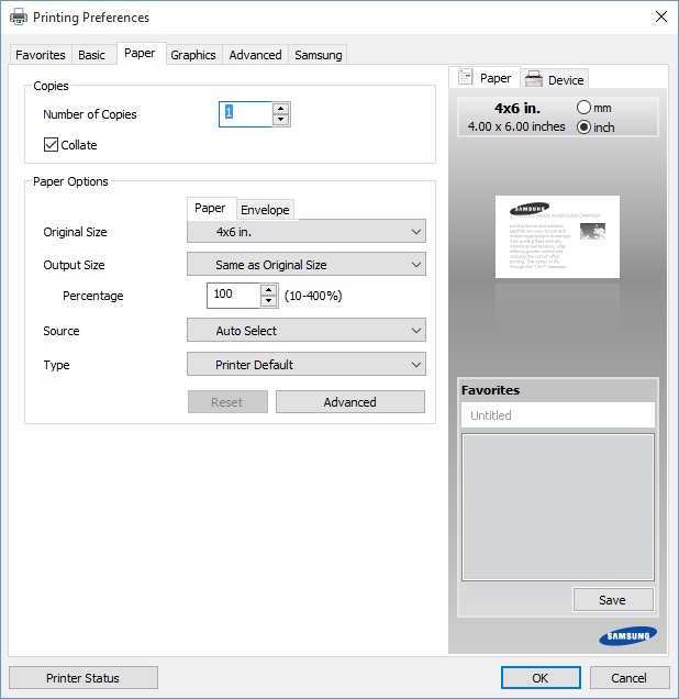
You will be able to select printer and fine tune printing preferences including paper size, layout, quality etc. prior to printing the label.
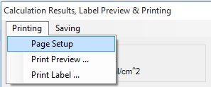
You can also click on Printing menu item, preview labels, make adjustment to page layout and printer settings setup prior to printing the labels.
Click on Library menu item and then select Fuses or Circuit Breakers to open up circuit protection device maintenance dialogue:
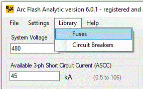
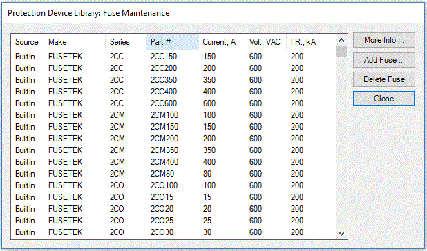
Figure 1. Fuse Maintenance Dialogue
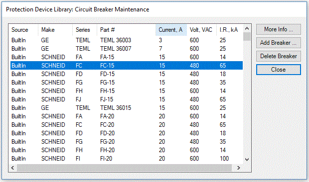
Figure 2. Circuit Breaker Maintenance Dialogue
You can click on column headings in maintenance dialogue to sort the data by make, series, part number, current, voltage, I.R. ratings etc.
You can add device if it is not already included in build-in fuse or circuit breaker library. Click [Add Fuse ...] or [Add Breaker ...] button respectively and fill out the new device information form.
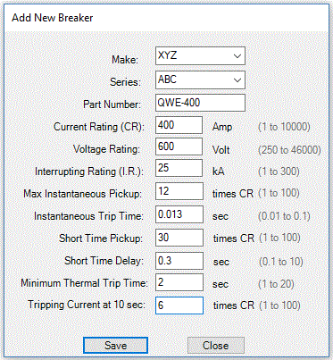
Figure 3. New Circuit Breaker Dialogue
Figure 4 below shows representative circuit breaker tripping curve.
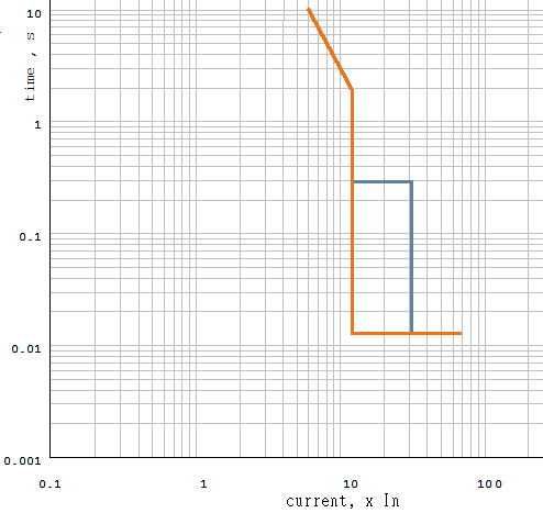
Figure 4. Sample Circuit Breaker Time-Current Characteristics
Follow vertical orange line until it intersects the horizontal axis. The point of intersection corresponds to Max Instantaneous Pickup on Figure 3 above.
Follow horizontal orange line until it intersects the vertical axis. The point of intersection corresponds to Instantaneous Trip Time on Figure 3 above.
Follow vertical blue line until it intersects the horizontal axis. The point of intersection corresponds to Short Time Pickup on Figure 3 above.
Follow horizontal blue line until it intersects the vertical axis. The point of intersection corresponds to Short Time Delay on Figure 3 above.
Find a point on breaker trip curve where maximum instantaneous trip line (upright orange line on Figure 4 below) breaks and starts departs from vertical. Follow from the point to the left until intersection with the time axis. The point of intersection corresponds to Minimum Thermal Trip Time on Figure 3 above.
Find ten (10) seconds point on time axis (vertical). Follow from it to the right until it intersects the breaker curve. Then follow that line straight down to the horizontal axis (current, Current Rating). The value corresponds to Tripping Current at 10 sec on Figure 3 above.
Click [Save] button below to add a new device into the database. The new device will now appear in protection device maintenance list.
To add a fuse, the program requires a set of five points from the fuse average melting time-current characteristics in 0.01 to 10 seconds interval. You need published fuse time-current characteristic or consult the fuse manufacturer to obtain the information.
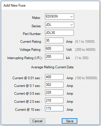
Figure 5. Fuse Information Dialogue
As an example, lets find out what current will open the fuse in 0.1 second. On the vertical axis (time in seconds) find 0.1 second and follow that line to the right until it intersects the fuse curve. Then follow that line straight down to the horizontal axis (current in Amperes) and read the current value. Repeat the steps above for remaining points.
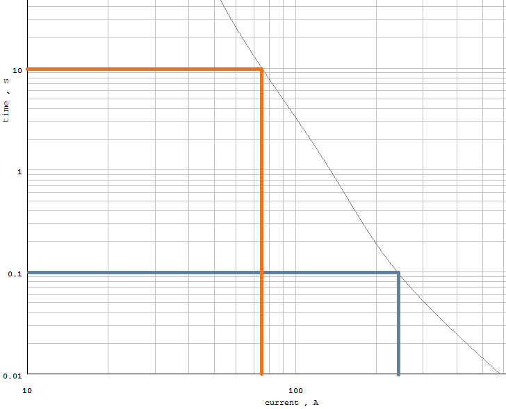
Figure 6. Sample Fuse Time-Current Characteristics
Additional information about ARCMASTER V1.0 software program
By clicking on Options -> Units menu option, metric (mm, Joules), imperial units (inches, calories) can be specified for distances (including gap between conductors, working distance, arc flash boundary, limited, restricted and prohibited boundaries), incident energies.
The program allows saving equipment configurations for future reference, including equipment name and class, fault type, total available short circuit fault current and power factor, part of the available fault current through protection device, gap between conductors, system voltage, working distance, upstream protective device information and arc duration.
ARCMASTER V1.0 performs arc flash boundary calculations based preset or on evaluated onset to second degree burn energy.
Create and save customized arc flash labels in English and a number of languages in electronic high resolution JPG, BMP (BitMap), GIF, TIF and PDF formats. The program features new "Warning" and "Danger" label layouts with orange, red strips on labels' top and bottom, as well as a plain background.
Benefits
- Calculator-style interface makes complex calculations easy to understand;
- Provide a safer working environment by specifying the proper level of personal protective equipment. Wearing inadequate clothing is dangerous for obvious reasons, but wearing too much clothing is dangerous due to limited mobility and visibility;
- Design safer power systems while insuring compliance with NEC 110.16, OSHA, NFPA 70E and CSA Z462 standards and regulations;
- Avoid potential fines, lost productivity, and increased insurance and litigation costs;
- Evaluate Threshold Incident Energy for a Second Degree Burn;
- Save time by generating arc flash warning labels in electronic high resolution JPG, BMP, TIF, GIF and PDF formats;
- Create, print, save warning labels;
- Save equipment data, calculation results for future reference or printing;
- Perform analysis using metric, imperial units, or a mix of both
System Requirements
ARCMASTER V1.0 was written in C# programming language, best viewed as a descendant of both C++ and Java languages. The language was developed by Microsoft within its .NET initiative and later approved as a standard by ECMA (ECMA-334) and ISO (ISO/IEC 23270:2006). The program requires Microsoft .NET Framework Version 3.5 or higher to run. If you experience problems running ARCMASTER V1.0 once you install it on your PC, please check the link below to identify .NET version set up on your system:
Determining Which Version of the .NET Framework Is Installed
If there is no Microsoft .NET framework installed on your system, or the installed .NET framework version is less than 3.5, please follow the
Download .NET Framework Version 3.5 link to update your system. Should you encounter any problem installing or running ARCMASTER V1.0, contact us and we will assist you in identifying and resolving the problem.


